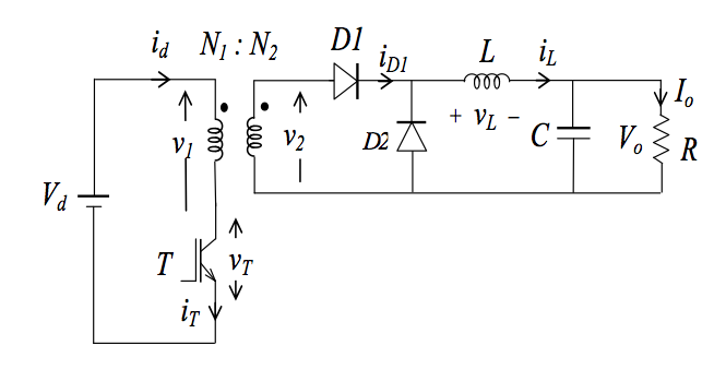
The forward converter is essentially a galvanically isolated buck converter.
Circuit Diagram[]
Analysis[]
The first relationship we wish to discover about the forward converter is the relationship between input voltage and output voltage during continuous conduction mode. As in the buck converter we will use the inductor and conservation of energy as the starting point.
The energy in the inductor over a full cycle is zero so


[]
Boundary between dis and cts Conduction[]
Next it is useful to find the minimum value for L for which the converter is still operating in continuous conduction mode. The boundary between cts and discts mode is when the minimum inductor current goes to zero.
Average inductor minus half the change equal minimum
From inductor equation


Using the relationship between voltage in and out

using minimum current is zero at boundary.

Forward converter with demagnetizing winding and energy return diode[]
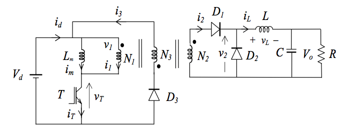
The introduction of a third winding and energy return diode improves the forward converter in two respects. Firstly it provides a pathway for the energy stored in Lm to return and secondly it also helps to reset the transformer flux quickly.
The equation describing the three winding transformer is

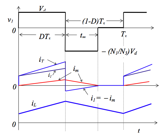
The energy return diode operates in the following manner, during Ton the middle winding conducts no current and the forward converter operates as previous specified. Although once T1 is turned off a voltage develops across as we have seen in previous circuits, although this voltage is limited by the third winding to . Also the current in Lm continues to flow circularly through L1 => , this allows current to follow back to the source.


Now we assume that the current falls to zero during as this is desirable.


During
and the conservation of energy implies


Hence for an any complete demagnetisation of the core will occur. Which is nice!

Now suppose the inductor requires for current to fall to zero this implies is the maximum amount of time available for current to fall to zero


Output Voltage Ripple[]
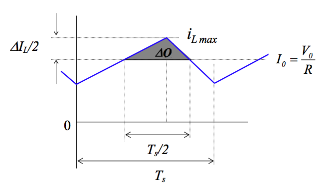
If our output voltage is constant the output capacitors average current is zero.
Hence and So capacitor essentially smooths the output current wave form, filling in the supply gaps when the inductor is out of energy.


Ok so we know
so


We then have essentially the area under capacitor current shown in figure above(triangle).

during Toff the voltage across the inductor is Vo.


Note:
is the cut off frequency of the LC filter, hence it is very desirable for

